Aufgabe 1.1: Dual-Slope–Verlustmodell
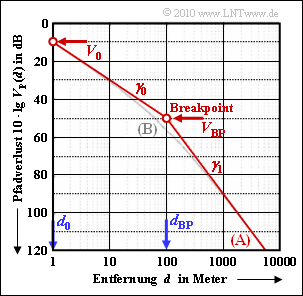
Zur Simulation des Pfadverlustes in städtischer Umgebung verwendet man oft das asymptotische Dual–Slope–Modell, das im Diagramm als rote Kurve dargestellt ist. Dieses einfache Modell ist durch zwei lineare Abschnitte gekennzeichnet, die durch den sog. Breakpoint (BP) getrennt sind:
- Für $d ≤ d_{\rm BP}$ gilt mit dem Exponenten $\gamma_0$:
- $V_{\rm P}(d) = V_{\rm 0} + \gamma_0 \cdot 10\,{\rm dB} \cdot {\rm lg} \hspace{0.15cm} ({d}/{d_0})\hspace{0.05cm}.$
- Für $d > d_{\rm BP}$ ist der Pfadverlustexponent $\gamma_1$ anzusetzen, wobei $\gamma_1 > \gamma_0$ gilt:
- $V_{\rm P}(d) = V_{\rm BP} + \gamma_1 \cdot 10\,{\rm dB} \cdot {\rm lg} \hspace{0.15cm} ({d}/{d_{\rm BP}})\hspace{0.05cm}.$
In diesen Gleichungen bedeuten:
- $V_0$ ist der Pfadverlust (in dB) bei $d_0$ (Normierungsdistanz).
- $V_{\rm BP}$ ist der Pfadverlust (in dB) bei $d=d_{\rm BP}$ ("Breakpoint").
Die Grafik gilt für die Modellparameter
- $d_0 = 1\,{\rm m}\hspace{0.05cm},\hspace{0.2cm}d_{\rm BP} = 100\,{\rm m}\hspace{0.05cm},\hspace{0.2cm} V_0 = 10\,{\rm dB}\hspace{0.05cm},\hspace{0.2cm}\gamma_0 = 2 \hspace{0.05cm},\hspace{0.2cm}\gamma_1 = 4 \hspace{0.3cm} \Rightarrow \hspace{0.3cm} V_{\rm BP} = 50\,{\rm dB}\hspace{0.05cm}.$
In den Fragen wird dieser abschnittsweise definierte Verlauf mit Profil (A) bezeichnet. Als zweite Kurve ist das Profil (B) eingezeichnet, das durch folgende Gleichung gegeben ist:
- $V_{\rm P}(d) = V_{\rm 0} + \gamma_0 \cdot 10\,{\rm dB} \cdot {\rm lg} \hspace{0.1cm} \left ( {d}/{d_0} \right ) + (\gamma_1 - \gamma_0) \cdot 10\,{\rm dB} \cdot {\rm lg} \hspace{0.1cm} \left (1 + {d}/{d_{\rm BP}} \right )\hspace{0.05cm}.$
Mit diesem Dual–Slope–Modell ist der gesamte Distanzverlauf geschlossen beschreibbar, und die Empfangsleistung hängt von der Distanz $d$ entsprechend der folgenden Gleichung ab:
- $P_{\rm E}(d) = \frac{P_{\rm S} \cdot G_{\rm S} \cdot G_{\rm E} /V_{\rm zus}}{K_{\rm P}(d)} \hspace{0.05cm},\hspace{0.2cm}K_{\rm P}(d) = 10^{V_{\rm P}(d)/10} \hspace{0.05cm}.$
Hierbei sind alle Parameter absolut einzusetzen, also nicht logarithmisch in dB. Die Sendeleistung wird zu $P_S = 5 W$ angenommen. Die weiteren Größen haben folgende Bedeutungen und Werte:
- $10 \cdot lg \ G_S = 17 dB$ (Gewinn der Sendeantenne),
- $10 \cdot lg \ G_E =\ – 3 dB$ (Gewinn der Empfangsantenne – also eigentlich ein Verlust),
- $10 \cdot lg \ V_{\rm zus} = 4 dB$ (Verlust durch Zuführungen).
Hinweis: Die Aufgabe gehört zum Kapitel 1.1.
Würde man das Profil (B) entsprechend
- $V_{\rm P}(d) = V_{\rm 0} + \gamma_0 \cdot 10\,{\rm dB} \cdot {\rm lg} \hspace{0.15cm} \left ( {d}/{d_0} \right ) + (\gamma_1 - \gamma_0) \cdot 10\,{\rm dB} \cdot {\rm lg} \hspace{0.1cm} \left ({d}/{d_{\rm BP}} \right )$
definieren, so wären Profil (A) und Profil (B) für $d ≥ d_{\rm BP}$ identisch. In diesem Fall würde jedoch im unteren Bereich ($d < d_{\rm BP}$) das Profil (B) oberhalb von Profil (A) liegen, und somit deutlich zu gute Verhältnisse suggerieren. Beispielsweise ergäbe sich für $d = d_0 = 1 m$ bei den zugrundeliegenden Zahlenwerten ein um 40 dB zu gutes Ergebnis:
- $V_{\rm P}(d) \hspace{-0.1cm} = \hspace{-0.1cm} V_{\rm 0} + \gamma_0 \cdot 10\,{\rm dB} \cdot {\rm lg} \hspace{0.1cm} \left ( {d}/{d_0} \right ) + (\gamma_1 - \gamma_0) \cdot 10\,{\rm dB} \cdot {\rm lg} \hspace{0.1cm} \left ({d}/{d_{\rm BP}} \right ) =\\ \hspace{-0.1cm} = \hspace{-0.1cm} 10\,{\rm dB} + 2 \cdot 10\,{\rm dB} \cdot {\rm lg} \hspace{0.1cm} \left ({1}/{100} \right ) = -30\,{\rm dB} \hspace{0.05cm}. $
Fragebogen
Musterlösung
- $$V_{\rm P}(d = 100\,{\rm m})\hspace{0.15cm} \underline{= 50\,{\rm dB}} \hspace{0.05cm}.$$
(2) Mit dem Profil (B) erhält man dagegen bei Verwendung von $V_0 = 10 \ dB$, $\gamma_0 = 2$ und $\gamma_1 = 4$:
- $$V_{\rm P}(d = 100\,{\rm m}) = 10\,{\rm dB} + 20\,{\rm dB}\cdot {\rm lg} \hspace{0.1cm}(100)+ 20\,{\rm dB}\cdot {\rm lg} \hspace{0.1cm}(2) \hspace{0.15cm} \underline{\approx 56\,{\rm dB}} \hspace{0.05cm}.$$
(3) Die Antennengewinne vom Sender (+17 dB) und Empfänger (–3 dB) sowie die internen Verluste der Basisstation (+4 dB) können zusammengefasst werden zu
- $$10 \cdot {\rm lg}\hspace{0.1cm} G \hspace{-0.1cm} = \hspace{-0.1cm} 10 \cdot {\rm lg}\hspace{0.1cm} G_{\rm S} + 10 \cdot {\rm lg} \hspace{0.1cm} G_{\rm E} - 10 \cdot {\rm lg}\hspace{0.1cm} V_{\rm zus} =\\ \hspace{-0.1cm} = \hspace{-0.1cm} 17\,{\rm dB} -3\,{\rm dB} - 4\,{\rm dB} = 10\,{\rm dB} \hspace{0.3cm} \Rightarrow \hspace{0.3cm} {G = 10} \hspace{0.05cm}.$$
Für das Profil (A) ergab sich folgender Pfadverlust:
$$V_{\rm P}(d = 100\,{\rm m})\hspace{0.05cm} {= 50\,{\rm dB}} \hspace{0.3cm} \Rightarrow \hspace{0.3cm} K_{\rm P} = 10^5 \hspace{0.05cm}.$$
Damit erhält man für die Empfangsleistung nach 100 Metern:
$$P_{\rm E}(d = 100\,{\rm m}) = \frac{P_{\rm S} \cdot G}{K_{\rm P}} = \frac{5\,{\rm W} \cdot 10}{10^5}\hspace{0.15cm} \underline{= 0.5\,{\rm mW}} \hspace{0.05cm}.$$
Bei Profil (B) ist die Empfangsleistung etwa um den Faktor 4 kleiner:
$$P_{\rm E}(d = 100\,{\rm m}) = \frac{5\,{\rm W} \cdot 10}{10^{5.6}}\approx \frac{5\,{\rm W} \cdot 10}{4 \cdot 10^{5}}\hspace{0.15cm} \underline{= 0.125\,{\rm mW}} \hspace{0.05cm}.$$
(4) Unterhalb des Breakpoints (d < 100 m) ist die Abweichung durch den letzten Summand von Profil (B) bestimmt:
$${\rm \Delta}V_{\rm P}(d = 50\,{\rm m}) \hspace{-0.1cm} = \hspace{-0.1cm} (\gamma_1 - \gamma_0) \cdot 10\,{\rm dB} \cdot {\rm lg} \hspace{0.1cm} \left (1 + {d}/{d_{\rm BP}} \right )=\\
\hspace{-0.1cm} = \hspace{-0.1cm} (4-2) \cdot 10\,{\rm dB} \cdot {\rm lg} \hspace{0.1cm} (1.5)\hspace{0.15cm}
\underline{\approx 3.5\,{\rm dB}} \hspace{0.05cm}.$$
(5) Hier liefert das Profil (A) mit $V_{\rm BP} = 50 \ dB$:
$$V_{\rm P}(d = 200\,{\rm m}) = 50\,{\rm dB} + 4 \cdot 10\,{\rm dB} \cdot {\rm lg} \hspace{0.1cm} (2)\hspace{0.15cm}
{\approx 62\,{\rm dB}} \hspace{0.05cm}.$$
Dagegen führt das Profil (B) zum Ergebnis:
$$V_{\rm P}(d = 200\,{\rm m}) \hspace{-0.1cm} = \hspace{-0.1cm} 50\,{\rm dB} + 20\,{\rm dB} \cdot {\rm lg} \hspace{0.1cm} (200)
+ 20\,{\rm dB} \cdot {\rm lg} \hspace{0.1cm} (3) = \\
\hspace{-0.1cm} = \hspace{-0.1cm} 10\,{\rm dB} + 46\,{\rm dB} + 9.5\,{\rm dB}
\hspace{0.15cm} {\approx 65.5\,{\rm dB}}$$
$$\Rightarrow \hspace{0.3cm} {\rm \Delta}V_{\rm P}(d = 200\,{\rm m}) = 65.5\,{\rm dB} - 62\,{\rm dB}\hspace{0.15cm}
\underline{\approx 3.5\,{\rm dB}} \hspace{0.05cm}.$$
Man erkennt, dass ΔVP nahezu symmetrisch zu d = dBP ist, wenn man die Entfernung d wie in der angegebenen Grafik logarithmisch aufträgt.
